 Image 1 of 1
Price: Contact Us
Email: sales@esi-technologies.com
Condition: USED IN GOOD CONDITION
Location: SKUE34
In Stock: 2
Product Specifications
Four quadrature decoder channels, independently programmable
Any channel may also act as a general purpose counter
24-bit resolution per channel
DC to 10 MHz general purpose count rates
DC to 1.2 MHz quadrature count rates (higher count rate in X1 and X2 modes)
Counters readable “on the fly”—24-bit output register
24-bit register for capture or match interrupt on each channel
Inputs may be differential or single-ended
Direct connection to most sensors
Programmable TTL resistor termination
Each channel has a programmable control input
Control input may be used to capture exact position on the fly
Each channel may be used as a general purpose up/down counter
Full programmable interrupt support
Programmable modes; programmable prescaler: 1X, 2X, 4X.
Individually programmable polarities for Count and Control inputs
All CMOS
Up to 16 counter channels per VME slot
cOUNTER cIRCUITRY• 24-bit Counter
• 24-bit Preset/Compare Register
• 24-bit Output Latch
• 24-bit Comparitor
• 6-bit Control Register
• 6-bit Input Control Register
• 6-bit Output Control Register
• 2-bit Quadrature Register
• Input Logic
• Output Logic
COUNTING AND CONTROL INPUT MODESQuadrature Counting
The X Input acts as the A Quadrature input.The Y Input acts as the B Quadrature input.
Control functions are available using the Z input.
Control functions may be executed through software.
Input may be multiplied by 1X, 2X or 4X.
Program Input Control Register [5..4] to 00.
Program Quadrature Control Register [1..0] to 01, 10, or 11.
up/Down counting
The X Input counts UP; the Y Input counts DOWN.Control functions are available using the Z input.
Control functions may be executed through software.
Program Input Control Register [0] to 0.
Program Quadrature Control Register [1..0] to 00.
Do not leave X nor Y inputs floating.
Ground unused X (–) or Y (–) input.
Count/Direction Counting
The X Input counts; the Y Input controls DIRECTION.Control functions are available using the Z input.
Control functions may be executed through software.
Program Input Control Register [0] to 1.
Program Quadrature Control Register [1..0] to 00.
Do not leave X nor Y inputs floating.
No control input
Leave control input open.Counting is enabled.
Program Input Control Register [5..4] to 00.
Program Channel Configuration Register [4..2] to 0xx.
Load Counter
Minimum pulse width is 80 nanoseconds.
Program Input Control Register [5..4] to 00.
Program Channel Configuration Register [4..2] to 111
for std polarity pulse, or 110 for inverted polarity.
This function may be used to establish a known
reference position in a mechanical system,
or to load starting value prior to down counting.
The Counter may also loaded from the Preset Register
under program control.
Load latch
An input pulse on Z will transfer the Counter value to the
Output Latch register.
Minimum pulse width is 80 nanoseconds.
Program Input Control Register [5..4] to 10.
Program Channel Configuration Register [4..2] to 111
for std polarity pulse, or 110 for inverted polarity.
This function may be used to capture a position
in a mechanical system, or to capture an intermediate
value while counting.
The value loaded is always valid, even if the Counter is
in the middle of a transition.
The Output Latch may also be loaded from the Counter
under program control.
input gate
Control Input level on Z enables or disables counting.Program Input Control Register [5..4] to 01.
Program Channel Configuration Register [4..2] to 101
for std polarity hold, or 100 for inverted polarity hold.
Opposite polarity enables counting.
counter Reset
An input pulse on Z will clear the Counter.Minimum pulse width is 80 nanoseconds.
Program Input Control Register [5..4] to 10.
Program Channel Configuration Register [4..2] to 101
for std polarity pulse, or 100 for inverted polarity.
This function may be used to establish a known
home or reference position in a mechanical system,
or to prepare for event counting.
The Counter may also be reset under program control.
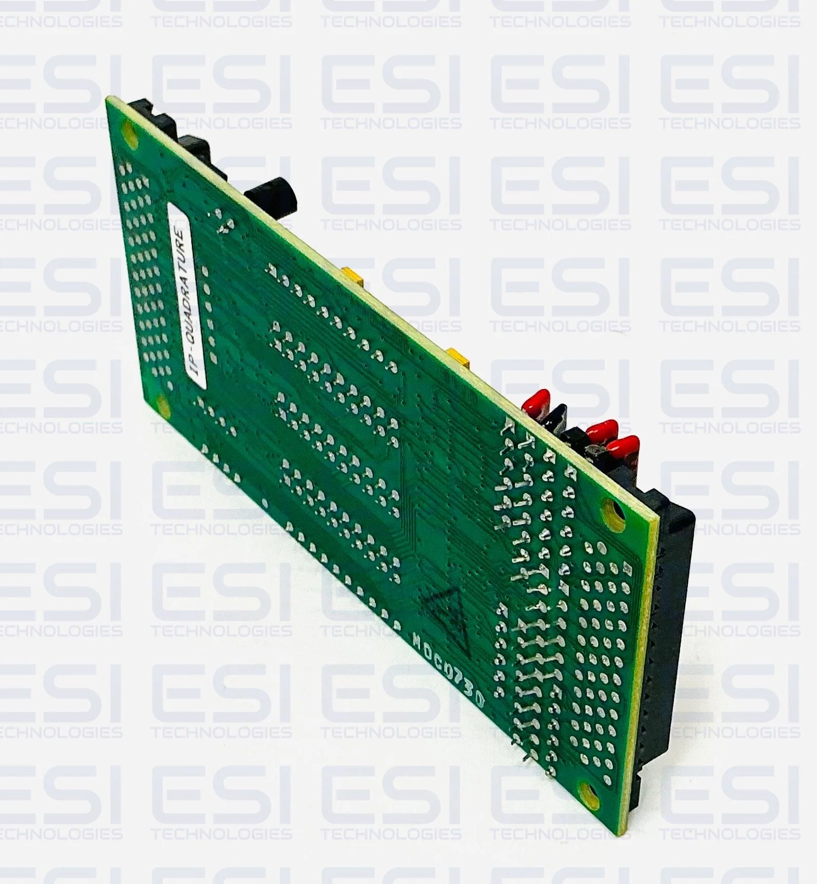
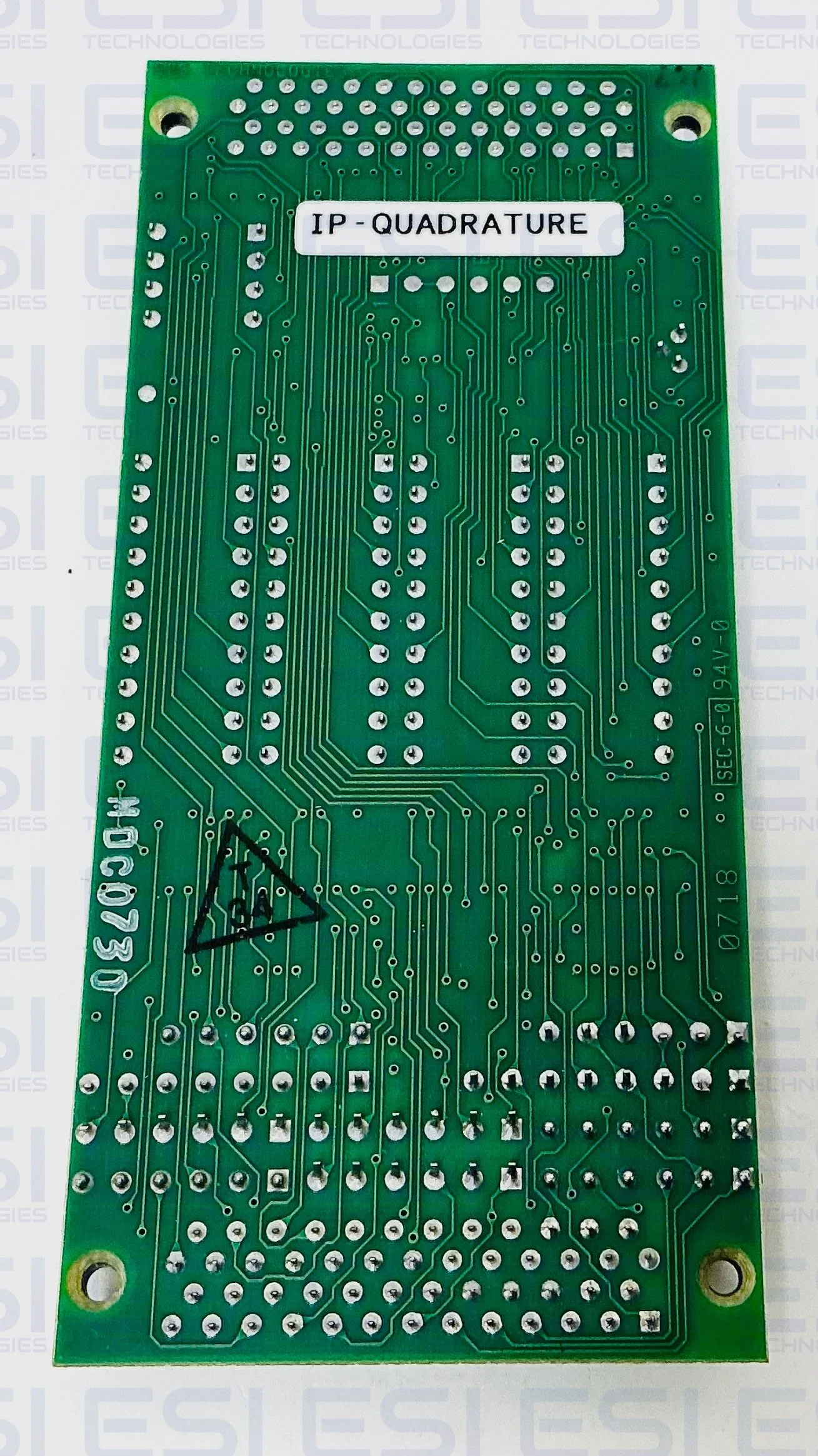
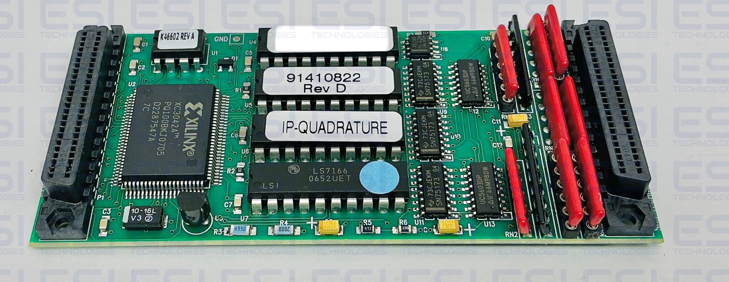
SBS Technologies’ IP-Quadrature provides high density, cost-effective flexible implementation of four quadrature decoder channels. Channels may also be used as general purpose counters.Four independent channels provide 24-bit resolution, programmable modes, programmable polarity, interrupt capability, differential or single-ended (RS-422 or TTL/CMOS) input, read-on-the-fly capability, and a count frequency of 0 to 10 MHz. Quadrature encoders are popular sensors that provide accurate, low cost incremental motion sensing. Most commonly, they are shaft encoders that provide 512 to 2048 counts per revolution. They are also commonly used as linear encoders with resolutions down to 0.005 inch. They are available in nearly any length desired. Most encoders are now optical, using molded assemblies consisting of a pair of LEDs, lenses, photosensors, and simple electronics. For rotary motion the assembly senses alternating opaque and clear lines on a rotating wheel. For linear motion the alternating lines may be on a fixed bar and the sensor assembly moves, or vice-versa. The pair of LED and photo-sensors are offset about one-half line width so that direction of motion may be sensed by observing the relative phase of the two outputs. Typical quadrature encoder outputs are a pair of digital logic signals that are nominally 90° out of phase. Some encoders also provide an “index” pulse output once per revolution to provide absolute position information. Most modern encoders run from +5 volts and provide CMOS/TTL logic outputs and/or RS-422 differential logic outputs. RS-422 is recommended where possible because of its inherent noise immunity and the ability to run long distances. TTL logic levels should normally be restricted to cables less than ten feet in length. Quadrature encoders are available from Hewlett-Packard, US Digital, and other sources. The general purpose input structure permits differential input from line drivers (RS-422 levels) or single-ended logic level input (“TTL”) directly from most sensors. Programmable TTL resistive terminators provide for flexible high-quality signal termination. There are three inputs per channel. For normal quadrature operation, the two quadrature inputs are called X and Y. These inputs are sometimes called A and B lines from encoders. The X and Y inputs are normally driven 90° out of phase. There is also a control input on each channel called Z. Its function is programmable, but it typically operates, if used, as an index or latch input. There is a programmable prescaler for each channel that may be set for X1, X2 or X4 operation. Vectored interrupts are fully supported. Interrupts are individually maskable. Selectable conditions are interrupt on borrow and interrupt on match (compare). RS-422 differential input lines are normally terminated with 120Ω resistors. Users may remove these socketed resistor networks or replace them with a different value if desired. Each channel consists of a programmable input section, a 24-bit up/down counter block, a 24-bit capture/match register, and a 24-bit output latch. The output latch permits accurate “on-the-fly” reading of quadrature position values. The capture/match register may be used as either a hardware “capture” register to record exact mechanical position or to provide an interrupt any arbitrary programmable quadrature position value.The all CMOS design is inherently low power. Up to 16 quadrature channels may be implemented in one host system slot.
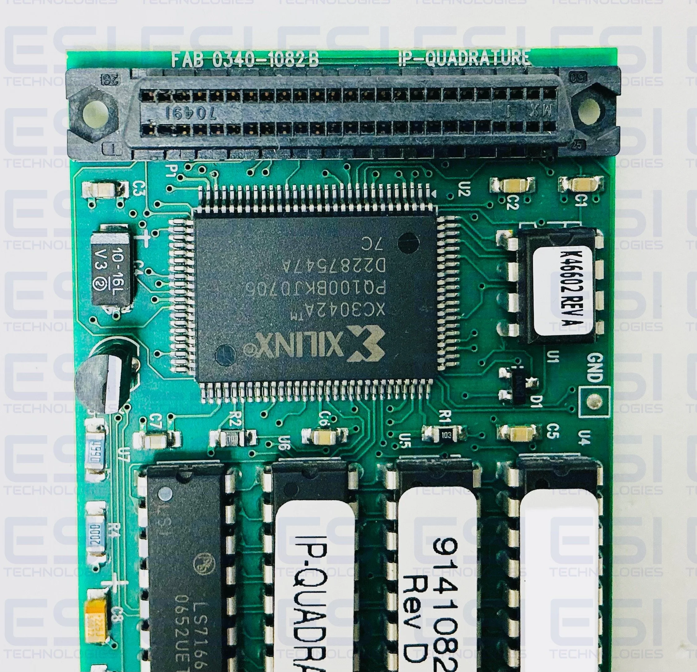
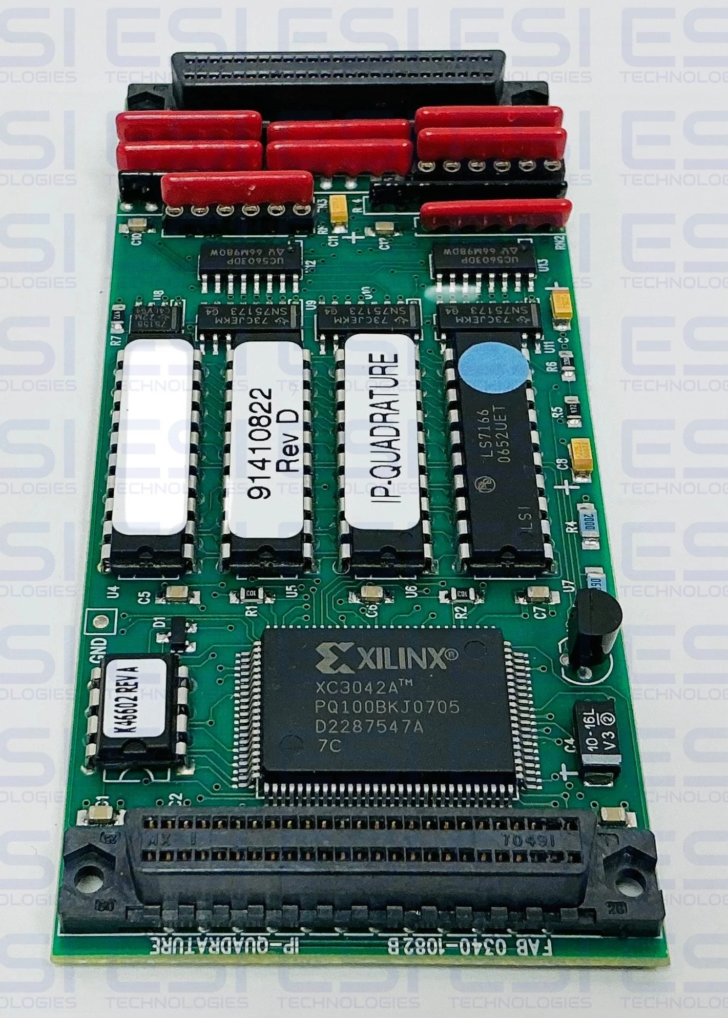
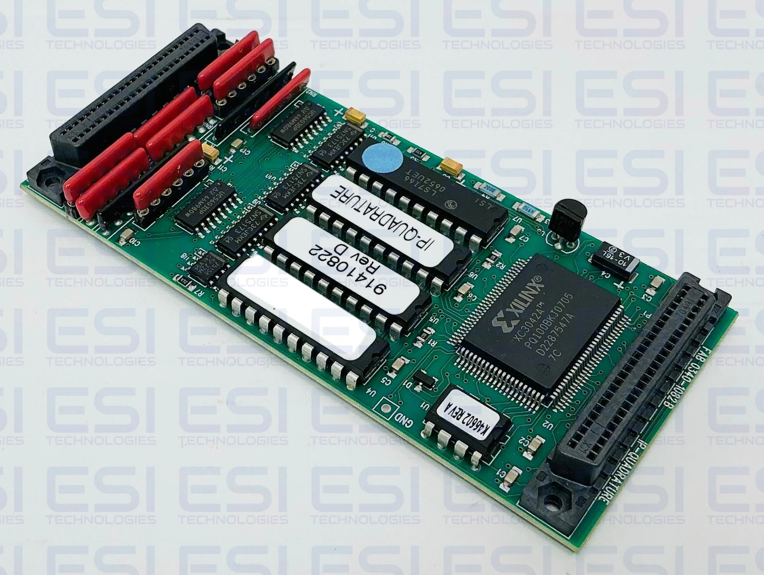
There are four quadrature decoder channels on the IP. The channels are independent, although some input termination options are implemented in groups of two channels. Each channel has three inputs, called X, Y, and Z. Normally X and Y are the two quadrature inputs and Z is the optional control or index input. If the channel is used as a general purpose counter then there are more programmable options for the use of X, Y and Z. Each channel has its own 24-bit count register, 24-bit preset/comparitor register and 24- bit output latch register, and its own control and status registers. The interrupt logic, polarity and function select logic, and IP interface logic is all located in a single 100-pin Xilinx programmable logic cell array (LCA). There are separate registers in the Xilinx LCA for each channel. These registers select the input polarities, counting functions, and interrupt control for the four channels.
The input circuitry consists of RS-422 differential receivers (comparitors) with resistors to implement termination options. Standard input is differential RS-422, terminated with 120Ω across the input. The termination resistors are socketed and may be removed or changed by the user. The resistor designators in Figure 3 are for reference here only; they do not correspond to designators on the actual IP. Alternatively the input may be TTL or similar logic levels. One side of the RS-422 input is biased at approximately 1.75 volts, permitting single-ended TTL, NMOS, CMOS, or optocoupler input to be directly connected. When running in this mode, one volt of hysteresis is implemented on the receiver to reduce noise. The IP-Quadrature can be converted from RS-422 input to TTL input by removing the RS-422 terminating resistor networks from their sockets. A termination network for TTL input may be switched in electronically through software. R1, as shown in Figure 3, is the termination resistor for the differential RS-422 input. The IP-Quadrature is shipped with a default termination resistor value of 120Ω. This resistor is implemented in SIP networks, and may be removed or changed by the customer, or by SBS for special orders. Typical terminator values range from 75Ω to 330Ω, and depend on the customer’s cabling and type of driver. This resistor should be removed for single-ended logic-level input
8 MHz Output Clock : The IP-Quadrature provides a RS-422 level buffered, 8 MHz clock output. This continuous clock may be connected by the user to the X or Y count input of any channel. The user then may use the Z control input as a gate, effectively making that channel into a gated 24-bit timer with a resolution of 125 nanoseconds when properly programmed.
Input Polarity: The polarity of both the X and Y inputs of each counter channel are individually programmable. Programmable polarity is implemented in the Xilinx LCA. There is a default polarity, called “standard” for both inputs. The standard polarity is represented by “0” in the polarity bits of the Channel Configuration Register for each counter. The timing diagrams below show the standard polarity. If the polarity bit in the Channel Configuration Register is set to “1”, then “reversed polarity” is set. The standard polarity is assumed in the text and figures in this document unless otherwise stated. Standard polarity signals consist of a “positive” level, pulse or edge in RS-422 input mode. (This means the + input has a higher, more positive, voltage than the – input.) In single-ended logic-level input mode, standard polarity consists of a “negative” level, pulse or edge. (This means the input is at logic zero, about 0.7 volts or less.) This definition of polarity is by convention. TTL signals have been historically “active low.” Many sensors and opto-couplers are “active low.” Polarity reversal on RS-422 signals may be accomplished by reversing the + and – inputs signals, or by programming the polarity bit in the Channel Configuration register to be a “1”. These do not have precisely the same effect, because floating inputs will have a different effect. In general, with standard polarity, a floating (disconnected) input goes to the most benign state. This is generally not the case for floating inputs where the polarity has been programmed for “reverse”.
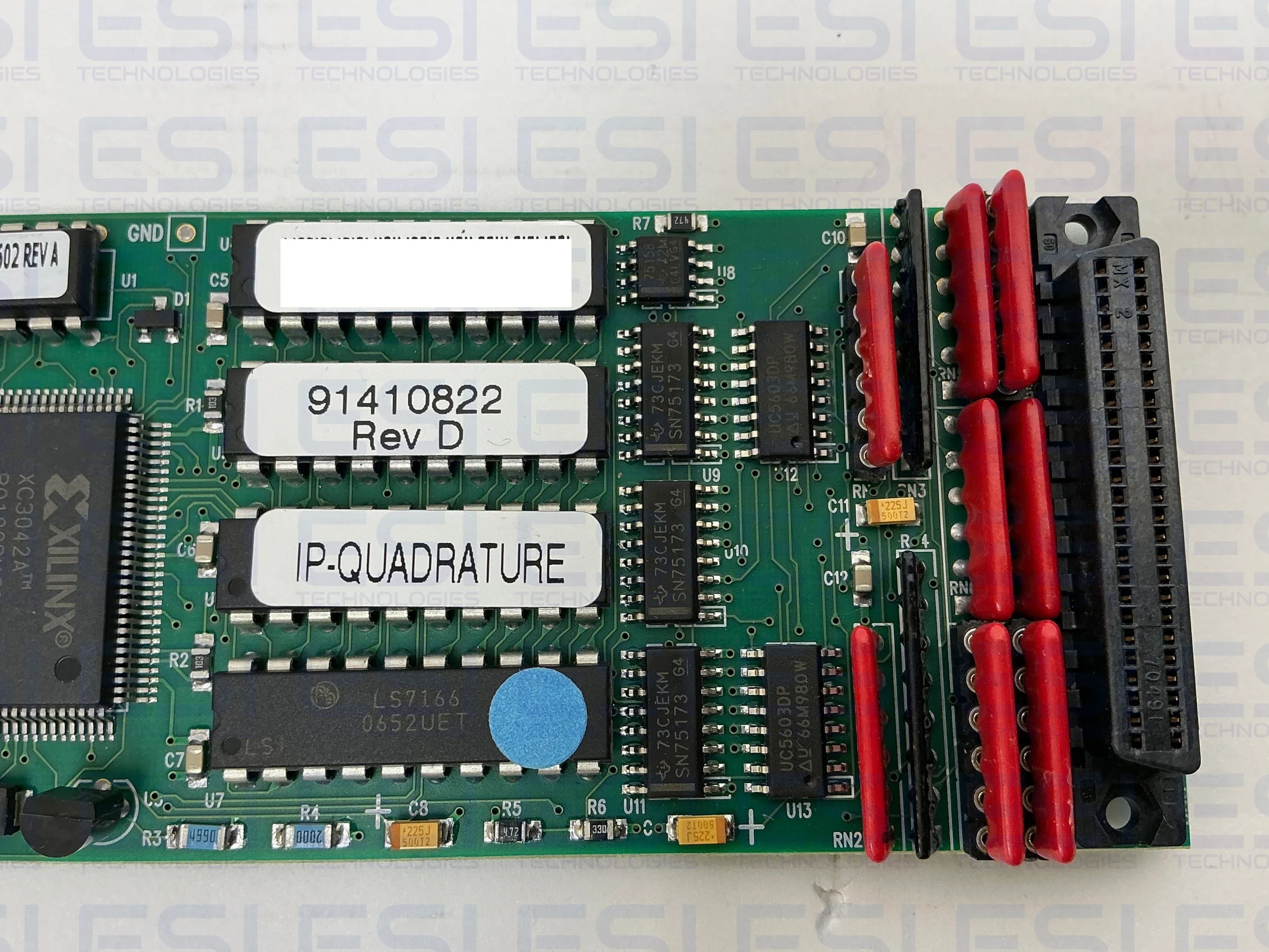
Counter Circuitry: The IP-Quadrature counters are implemented with an LS7166 IC. There is one IC per channel; four LS7166 ICs per IP-Quadrature.inputs. Alternatively each channel may operate as a general purpose counter, where the X and Y inputs operate as either Count-Up and Count-Down pulse inputs, or as Count input and Direction input respectively. Counting down is often preferred for interrupts, because underflow (“borrow”) may be programmed to cause an interrupt. An interrupt may also be generated on a Match. The Preset/Compare Register may be programmed to any value, including $FFFFFF or $000000 (to simulate interrupt on “overflow”). Both underflow and overflow have dedicated flip-flops that may be read by reading the counter’s control register. The counter registers and flip-flops are accessed as registers in the LS7166 counter IC. The LS7166 IC has two count inputs, called A and B at the chip, and two control inputs, which may each be programmed for one of two functions. Both the A and B count inputs and the two control inputs on the LS7166 are driven by the Xilinx LCA, which provides routing and polarity functions. The X Input to the IP-Quadrature is normally routed to the A input, and the IP's Y Input is routed to the chip's B input. The IP's Z input is routed to either of the two Control Inputs on the chip. The polarity of all three input signals is individually programmable. There is a software controlled gating bit implemented in the Xilinx LCA for the Z input. There are software controlled gating bits for the X and Y inputs implemented in the LS7166. In general, counting modes and control functions are available independently. Figure 9 lists basic counting modes and Figure 10 lists basic control functions. If no Control Function is desired, the Z Control input may be left unconnected. The 24-bit Preset/Compare Register has two functions. It is used when the host software wishes to load a specific value into the Counter, as is typical for down counting. This register may also be transferred into the Counter by the Control input, if the appropriate control function has been programmed. The 24-bit Preset/Compare Register is also used to produce an interrupt when the Counter reaches a particular value. Note that this register may be used to first load the Counter, then changed to support the interrupt-on-match function. The register may be changed while the Counter is operating. Multiple Match interrupts can be programmed by reloading this register after each interrupt (making sure after doing so that the Counter has not already passed the desired interrupt point). The 24-bit Output Latch has two functions. It is used to read the Counter. The 24-bit Counter may not be read directly, but is first transferred to the Output Latch to provide 16 reliable on-the-fly reading. The transfer is initiated by the host software setting bit [1] of the counter’s control register to one. After the Output Latch has been read, bit [1] of the control register is automatically reset back to zero. The host software needs to access the control register only once to read the Counter. The 24-bit Output Latch is also used as a hardware capture register. In this mode the Z control input to be used as a hardware trigger to initiate the transfer of the Counter to the Output Latch, if the appropriate control function has been programmed.
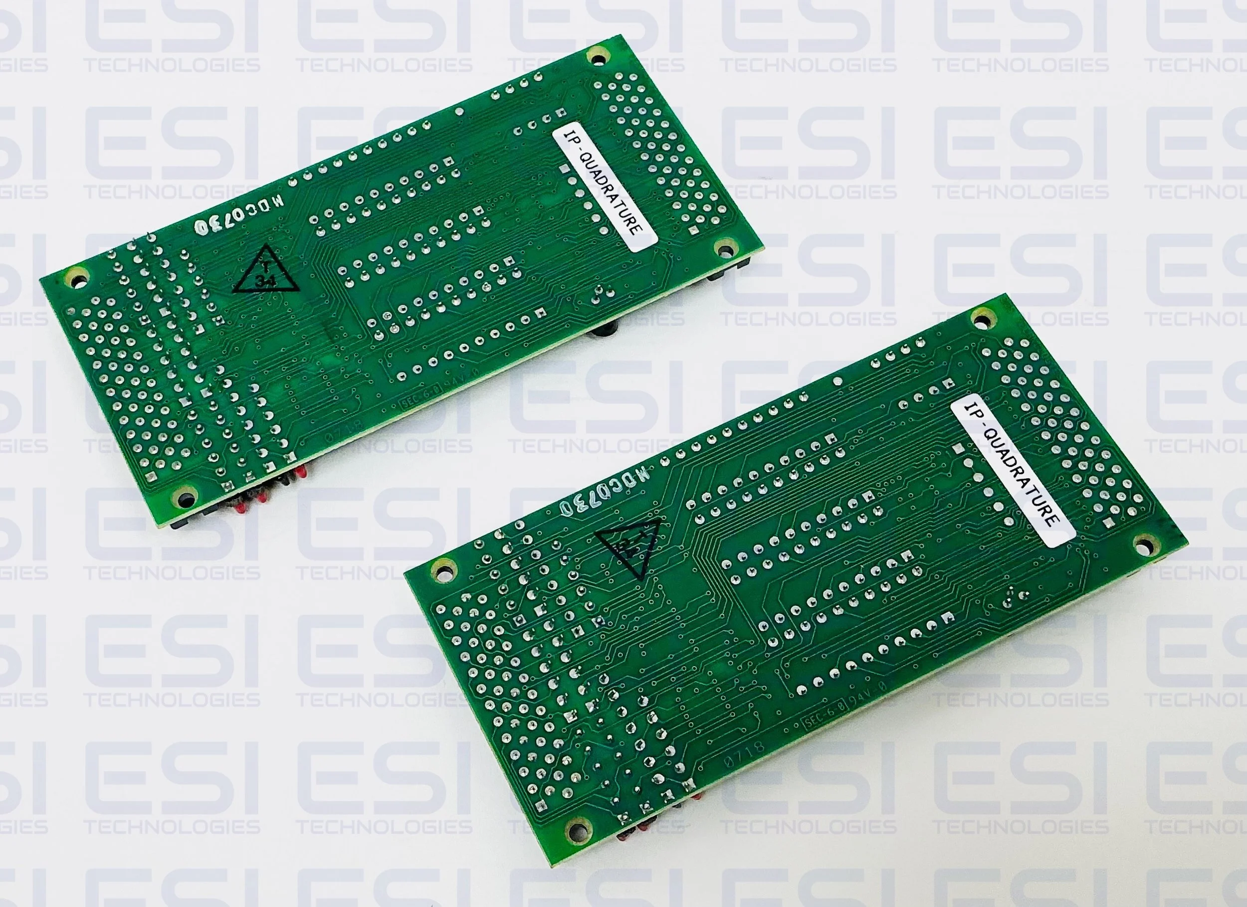
Alternative Part No. 91410822, 0340-1082 B
NSN (Product Family): 5990-01-512-9129 / 5990015129129
Product Manual
Product Images