 Image 1 of 1
Product Specifications
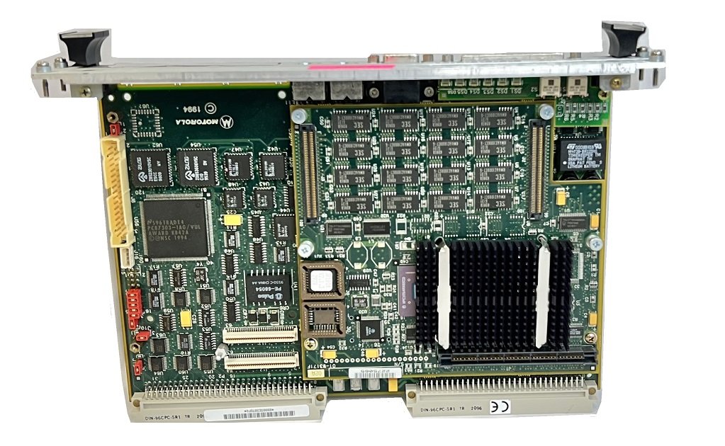
Boot ROM Two 32-pin PLCC sockets (1MB Flash)
Software-readable header 8-bit readable header (4 bits reserved for firmware, 4 bits user-definable)
Real-time clock 8KB NVRAM with RTC and battery backup (SGS-Thomson M48T18)
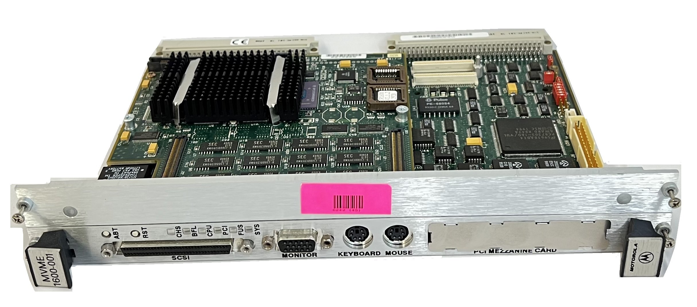
Switches RESET and ABORT
Status LEDs Six: CHS, BFL, CPU, PCI, FUS, and SYS
Tick timers Four programmable 16-bit timers (one in S82378ZB ISA bridge; three in Z8536 CIO device)
Watchdog timer Provided in VMEchip2
Interrupts Eight software interrupts
VME I/O VMEbus P2 connector
Serial I/O 2 async ports, 2 sync/async ports via P2 and MVME760 transition module (async: PC87303 SIO; sync: Zilog 85230 ESCC)
2 async ports via P2 and MVME712M transition module; 2 sync/async ports via P2 and MVME712M or front panelParallel I/O IEEE1284 Bidirectional parallel port (PC87303 SIO) via P2 and transition module
SCSI I/O 16-bit SCSI interface (NCR 53C825) via front panel
8-bit SCSI interface (NCR 53C810) via P2 and MVME712M transition module
Ethernet I/O AUI and 10BaseT connections via P2 and MVME760 transition module
AUI connection via P2 and MVME712M transition module; 10BaseT connection via front panel
PCI interface One IEEE P1386.1 PCI Mezzanine Card (PMC) slot
Keyboard/mouse interface Support for keyboard and mouse input (PC87303 SIO) via front panel
Graphics port Super VGA high-resolution color graphics (CL-GD5446 graphics accelerator)
Manufactured by Motorola. Refurbished in good condition.
On the MVME1600-001 base board, either the standard serial console port (COM1) or the on-board video (VGA) port can serve as the PPCBug firmware console port. MVME1600-001 is an SBC factory-configured in system controller mode. This means that the MVME1600-001 assumes the role of system controller at system power-up or reset. The MVME1600-001 base board furnishes +12Vdc, –12Vdc, and +5Vdc power to the MVME760 transition module through polyswitches (resettable fuses) F4, F2, and F3. The MVME760 uses these voltage sources to power the serial port drivers and any LAN transceivers connected to the transition module. The FUS LED (DS5) on the MVME1600-001 front panel illuminates when all three voltages are available. The fused +5Vdc power is also supplied to the base board’s keyboard and mouse connectors and to the 14-pin combined LED-mezzanine/remotereset connector, J1. In addition, the MVME1600-001 base board provides +5Vdc to the SCSI bus TERMPWR signal through fuse F1, located near the front panel SCSI connector. The FUS LED (DS5) on the front panel monitors the SCSI bus TERMPWR signal along with the other operating voltages; when the MVME1600-001 is connected to an SCSI bus, either directly or via the MVME760 module, SCSI terminator power helps illuminate the FUS LED. The MVME1600-001 base board supplies a SPEAKER_OUT signal to the 14-pin combined LED-mezzanine/remote-reset connector, J1. When J1 is used as a remote reset connector with the LED mezzanine removed, the SPEAKER_OUT signal can be cabled to an external speaker.
SKU#1
Qty 1
Alternative P/N: MVME 1600-001, MVME1600-001, MVME1600 001, MVME600 001
Product Manual
Product Images