 Image 1 of 1
Price: Contact Us
Email: sales@esi-technologies.com
Condition: NEW
Location: SKUE19-2
In Stock: 1
Product Specifications
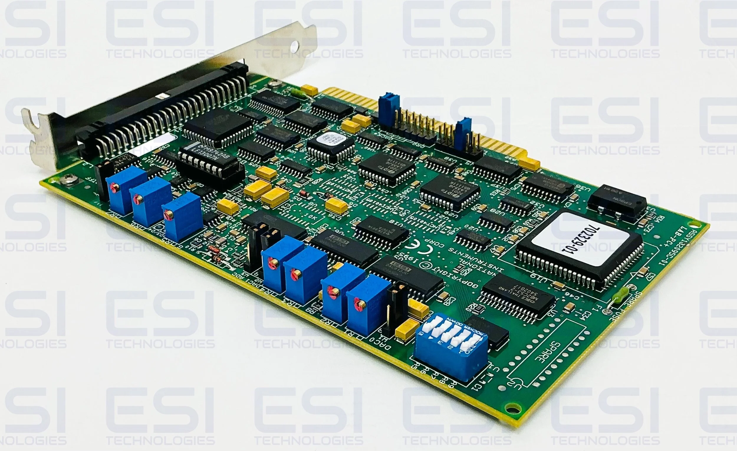
The Lab-PC+ is a low-cost multifunction analog, digital, and timing I/O board for the PC. The Lab-PC+ contains a 12-bit successive-approximation ADC with eight analog inputs, which can be configured as eight single-ended or four differential channels. The Lab-PC+ also has two12-bit DACs with voltage outputs, 24 lines of TTL-compatible digital I/O, and six 16-bit counter/timer channels for timing I/O. The low cost of a system based on the Lab-PC+ makes it ideal for laboratory work in industrial and academic environments. The multichannel analog input is useful in signal analysis and data logging. The 12-bit ADC is useful in high-resolution applications such as chromatography, temperature measurement, and DC voltage measurement. The analog output channels can be used to generate experiment stimuli and are also useful for machine and process control and analog function generation. The 24 TTL-compatible digital I/O lines can be used for switchingexternal devices such as transistors and solid-state relays, for reading the status of external digital logic, and for generating interrupts. The counter/timers can be used to synchronize events, generate pulses, and measure frequency and time. The Lab-PC+, used in conjunction with the PC, is a versatile, cost-effective platform for laboratory test, measurement, and control.
Software Programming Choices
There are several options to choose from when programming your National Instruments DAQ and SCXI hardware. You can use LabVIEW, LabWindows/CVI, NI-DAQ, or register-level programming.
LabVIEW and LabWindows/CVI Application Software
LabVIEW and LabWindows/CVI are innovative program development software packages for data acquisition and control applications. LabVIEW uses graphical programming, whereas LabWindows/CVI enhances traditional programming languages. Both packages include extensive libraries for data acquisition, instrument control, data analysis, and graphical data presentation. LabVIEW features interactive graphics, a state-of-the-art user interface, and a powerful graphical programming language. The LabVIEW Data Acquisition VI Library, a series of VIs for using LabVIEW with National Instruments DAQ hardware, is included with LabVIEW. The LabVIEW Data Acquisition VI Libraries are functionally equivalent to the NI-DAQ software. LabWindows/CVI features interactive graphics, a state-of-the-art user interface, and uses the ANSI standard C programming language. The LabWindows/CVI Data Acquisition Library, a series of functions for using LabWindows/CVI with National Instruments DAQ hardware, is included with the NI-DAQ software kit. The LabWindows/CVI Data Acquisition libraries are functionally equivalent to the NI-DAQ software. Using LabVIEW or LabWindows/CVI software will greatly reduce the development time for your data acquisition and control application.
NI-DAQ Driver Software
The NI-DAQ driver software is included at no charge with all National Instruments DAQ hardware. NI-DAQ is not packaged with signal conditioning or accessory products. NI-DAQ has an extensive library of functions that you can call from your application programming environment. These functions include routines for analog input (A/D conversion), buffered data acquisition (high-speed A/D conversion), analog output (D/A conversion), waveform generation (timed D/A conversion), digital I/O, counter/timer operations, SCXI, RTSI, calibration, messaging, and acquiring data to extended memory. NI-DAQ has both high-level DAQ I/O functions for maximum ease of use and low-level DAQ I/O functions for maximum flexibility and performance. Examples of high-level functions are streaming data to disk or acquiring a certain number of data points. An example of a low-level function is writing directly to registers on the DAQ device. NI-DAQ does not sacrifice the performance of National Instruments DAQ devices because it lets multiple devices operate at their peak performance.
Board Configuration
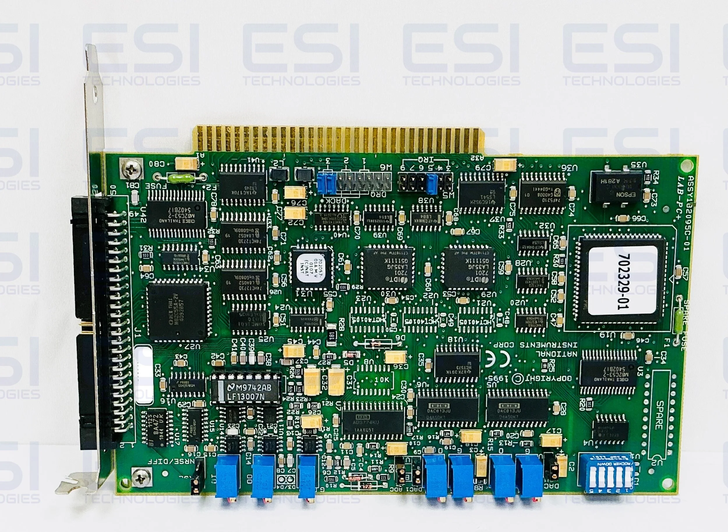
The Lab-PC+ contains six jumpers and one DIP switch to configure the PC bus interface and analog I/O settings. The DIP switch is used to set the base I/O address. Two jumpers are used as interrupt channel and DMA selectors. The remaining four jumpers are used to change the analog input and analog output circuitry. The parts locator diagram in Figure 2-1 shows the Lab-PC+ jumper settings. Jumpers W3 and W4 configure the analog input circuitry. Jumpers W1 and W2 configure the analog output circuitry. Jumpers W6 and W5 select the DMA channel and the interrupt level, respectively.
PC Bus Interface
The Lab-PC+ is configured at the factory to a base I/O address of hex 260, to use DMA Channel 3, and to use interrupt level 5. These settings (shown in Table 2-1) are suitable for most systems. If your system, however, has other hardware at this base I/O address, DMA channel, or interrupt level, you will need to change these settings on the other hardware or on the Lab-PC+
Base I/O Address Selection
The base I/O address for the Lab-PC+ is determined by the switches at position U1. the switches are set at the factory for the base I/O address hex 260. This factory setting is used as the default base I/O address value by National Instruments software packages for use with the Lab-PC+. The Lab-PC+ uses the base I/O address space hex 260 through 27F with the factory setting.
DMA Channel Selection
The Lab-PC+ uses the DMA channel selected by jumpers on W6 (see Figure 2-1). The Lab-PC+ is set at the factory to use DMA Channel 3. This is the default DMA channel used by the Lab-PC+ software handler. Verify that other equipment already installed in your computer does not use this DMA channel. If any device uses DMA Channel 3, change the DMA channel used by either the Lab-PC+ or the other device. The Lab-PC+ hardware can use DMA Channels 1, 2 and 3. Notice that these are the three 8-bit channels on the PC I/O channel. The Lab-PC+ does not use and cannot be configured to use the 16-bit DMA channels on the PC AT I/O channel.
DMA Channel Selection
The Lab-PC+ uses the DMA channel selected by jumpers on W6 (see Figure 2-1). The Lab-PC+ is set at the factory to use DMA Channel 3. This is the default DMA channel used by the Lab-PC+ software handler. Verify that other equipment already installed in your computer does not use this DMA channel. If any device uses DMA Channel 3, change the DMA channel used by either the Lab-PC+ or the other device. The Lab-PC+ hardware can use DMA Channels 1, 2, and 3. Notice that these are the three 8-bit channels on the PC I/O channel. The Lab-PC+ does not use and cannot be configured to use the 16-bit DMA channels on the PC AT I/O channel.
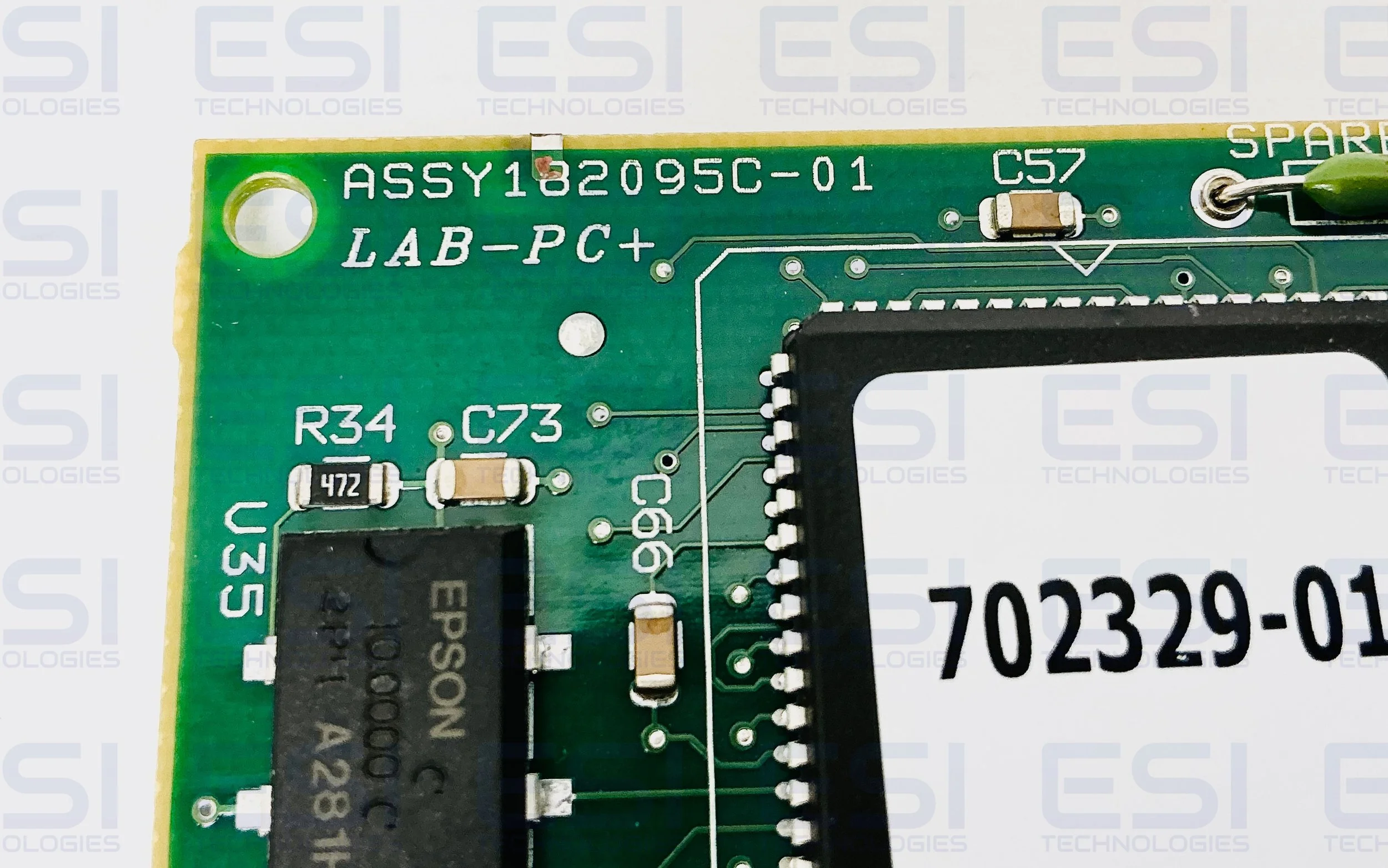
Alternative Part No. LAB-PC+, 182095C-01, FAB 182097C-01
Product Manual
Product Images